The concepts of dimensional tolerancing is an accepted part of manufacturing. Unfortunately, the misapplication of it can cause a host of problems. For instance, an overly stringent tolerance might require that parts go to a secondary grinding or EDM operation for completion, unnecessarily increasing costs and lead-time. Tolerances that are “too loose” or that aren’t in line with those of mating parts can make assembly impossible, leading to required rework, or in the worst case, making the finished product unusable.
To help avoid these unpleasant situations, this design tip includes some guidelines on how to properly apply part tolerances, along with a few definitions of the more commonly used callouts.
Standardized Tolerances for CNC Machining
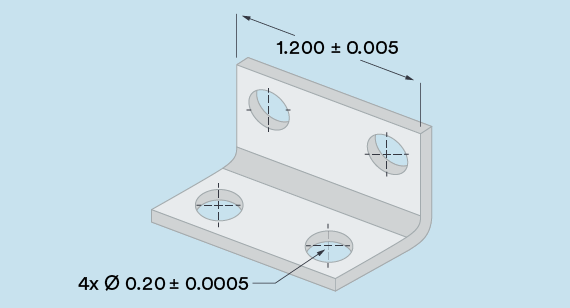
The standard prototype and production machining tolerance at AMPERE FUTURE is +/- 0.005 in. (0.13mm). This means any part feature’s location, width, length, thickness, or diameter will not deviate by more than 0.005 in. from nominal. For example, the 1.200 in. (30.48mm)-wide bracket you’re planning to order will measure betweenc(30.353 and 30.607mm) across, while the 0.200 in. (5.08mm) hole on one leg of that bracket will come in at 0.195 to 0.205 in. (4.953 to 5.207mm) diameter.
That’s pretty close, but we can often achieve even greater accuracy, provided you make us aware of your requirements. For these and other exceptions, please be sure to note them on your part design when you upload the file(s) for quoting.
Tolerancing Guidelines
Also, be aware that these are bilateral tolerances. If expressed in unilateral terms, the standard tolerance would read +0.000/- 0.010 in. (or +0.010/- 0.000 in.) while a limit-based tolerance in our bracket example would be 1.195 and 1.205 in.
All are acceptable, as are metric values, provided that you spell them out on the design. And to avoid confusion, please stick with the “three place” dimensions and tolerances shown.
Surface Roughness Considerations for Machining Tolerances
There’s more to part tolerancing than length, width, hole size, etc. There’s also surface roughness, which in the standard offering is equal to 63 µ in. for flat and perpendicular surfaces, and for curved surfaces, 125 µ in. or better.
This is an adequate finish for most uses, but for cosmetic surfaces on metal parts, we’re generally able to improve appearance through light bead blasting. if you’re in need of something smoother, note it on your design and we’ll do our best to accommodate you.
Geometric Dimensioning and Tolerancing
Here’s another consideration.GD&T tolerancing provides a deeper level of quality control that includes relationships between various part features as well as form and fit qualifiers. Below are a few of the more common ones:
- Flatness: Milled surfaces are generally quite flat, but due to internal material stress or clamping forces during the machining process, some warpage can occur once the part has been removed from the machine, especially on thin-walled and plastic parts. A GD&T flatness tolerance controls this by defining two parallel planes within which a milled surface must lie.
- Cylindricity: For the same reasons that most milled surfaces are quite flat, most holes are quite round, as are turned surfaces. Using cylindricity—defined as two concentric cylinders inside of which the machined hole must lie—manufacturers eliminate this unlikely situation.
- Concentricity: The rings on a bullseye are concentric, just as the wheels on your car are concentric to the axle. If a drilled or reamed hole must run perfectly true to a coaxial counterbore or circular boss, a concentricity callout is the best way to assure this.
- Perpendicularity: As its name implies, perpendicularity determines the maximum deviation of a horizontal machined surface to a nearby vertical surface. It can also be used to control the squareness of a turned shoulder to an adjacent diameter or the center axis of the part.
There are additional considerations to GD&T, including parallelism, straightness, profile, and angularity. As with any other non-standard tolerances, however, they must be called out on the design at the time of upload.
Ultimately, we’re here to support your project from prototyping to production, whatever the tolerance requirements. This is because we offer both a fully automated machining option for fast turnaround or a high-precision option with extended milling and post-machining capabilities for the highest complexity parts. We have all of your CNC milling and turning needs covered.